Sample work product
Portable battery energy storage, 480 V three-phase
A complete design and documentation package, reproduced as a redacted sample. The client's identity, the equipment served, site details, pricing, and fabrication instructions have been removed. The engineering content, the code citations, and the open compliance items are exactly as delivered.
What the system is
A portable battery energy storage system supplying 480 V three-phase to a tower crane, recharged from ordinary 120 V shore power. An unusually demanding case: high peak draw, a variable-frequency drive front end, no utility service, and a portable enclosure requiring third-party field evaluation.
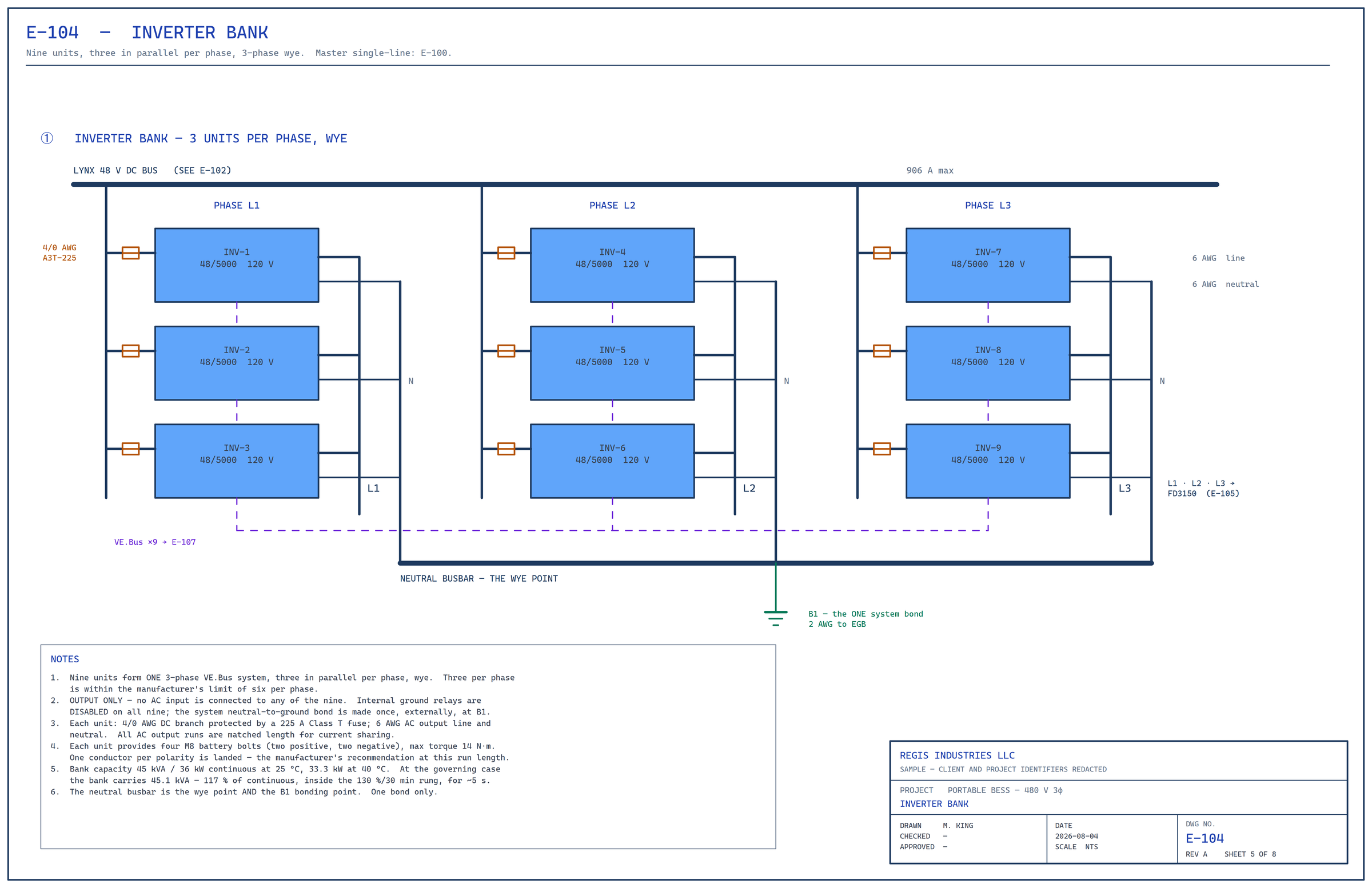
Twelve 48 V lithium iron phosphate packs on a 1,000 A busbar platform. Nine inverters configured as one three-phase wye, three in parallel per phase, plus a tenth inverter dedicated to shore charging. A floating DC bus with insulation monitoring. A 40 kVA drive isolation transformer stepping 208 V delta to a solidly grounded 480Y/277 V system. A 100 A shunt-trip output breaker and camlock connectors to the crane.

What is in the package
- Eight drawing sheets, E-100 through E-107: a master single-line plus seven detail sheets showing each unit and its connections, drawn to a documented drafting standard with IEEE 315 symbols.
- A bill of materials listing manufacturer, exact part number, quantity, and the certifications each component holds, with the certifying body and certificate numbers.
- A load test and margin verification summary: a measured working day and the 25 percent margin carried through every stage.
- The sizing justification: the chain stage by stage, battery to crane, with every decision defended in writing.
- The load basis summary reproduced below.
The load basis: measured, not calculated
- A full working day on the crane this system supplies: 8.1 hours continuous, about 43 lift cycles.
- A power analyser clamped on the 208 V bus. Power factor 0.93; crest factor 2.2 to 2.9, a VFD front end inside its 3:1 rating.
- Total energy across the day: about 13 kWh.
- Worst one-minute average: 9.8 kVA. Worst routine lift: 30.5 kVA. Worst measured second: 35.0 kVA, 32.4 kW.
- The crane's catalog rating, 55 kVA, is unmeasured and carried as a reference only.
The governing case is the worst measured second plus 25 percent: 43.8 kVA at the crane, 52.6 A at 480 V. It reflects through the transformer at 97 percent efficiency to 45.1 kVA and 125.2 A at the 208 V inverter bus, 906 A on the DC bus, and 75.5 A per battery pack. The real event lasts about five seconds.
Stage by stage at the governing case
| Stage | Demand | Limit | Loading | Sheet |
|---|---|---|---|---|
| Crane feeder, 2 AWG at 75 °C | 52.6 A | 115 A | 46 % | E-106 |
| Output breaker, 100 A frame at 80 % | 52.6 A | 80 A | 66 % | E-106 |
| Transformer, continuous rating | 52.6 A | 48.1 A | 109 % | E-105 |
| Transformer, 150 % for 60 s rung | 52.6 A | 72.2 A | 73 % | E-105 |
| Primary breaker and 1/0 conductors | 125.2 A | 150 A | 84 % | E-105 |
| Inverter bank, continuous at 25 °C | 45.1 kVA | 38.7 kVA | 117 % | E-104 |
| DC busbar | 906 A | 1,000 A | 91 % | E-102 |
| Battery pack, integral breaker | 75.5 A | 125 A | 60 % | E-101 |
| DC branch and fuse, 4/0 at 75 °C | 100.7 A | 230 A / 225 A | 44 % / 45 % | E-102 |
Two stages enter documented short-duration overload windows by design: the transformer and the inverter bank. Both are shown against the applicable rung, not only against their continuous ratings. The inverter bank sits inside its 130 percent for 30 minutes rung against an event lasting about five seconds; at 40 °C ambient the figure rises to 126 percent, still inside the same rung.
Two numbers we state rather than bury
Per-pack DC current: 75.5 A against a 75 A certified line. At the governing case each pack draws 0.7 percent above the figure on the battery's energy-storage-system certificate, for roughly five seconds. The manufacturer's manual permits 100 A continuous with higher short-duration tiers, all enforced by the integral battery management system, and the system's continuous duty is 65 A per pack. It is not a hardware limit, but it is a certified line, so it is stated, and confirmation has been requested from the manufacturer that the certificate figure is a continuous rating with the duration tiers remaining available.
DC busbar at 91 percent. 906 A of a 1,000 A rating. Not exceeded, but the headroom that is 22 percent at the design point narrows to 9 percent here. No design action; recorded, and monitored during the thermal test.
Two decisions, explained
An 80 percent rated output breaker. Where a moulded-case breaker's continuous rating basis is not stated, the conservative assumption is 80 percent of frame, so a 100 A frame gives 80 A continuous and that figure is used throughout. At the governing case the breaker carries 52.6 A, 66 percent of that. If the frame proves to be 100 percent rated, the same load falls to 53 percent: the confirmation can only improve the position, because the conservative case is the one already designed to.
A 40 kVA transformer. The worst measured demand, 35 kVA, is 36 percent below the crane's catalog figure. With 25 percent applied it becomes 43.8 kVA: 109 percent of the transformer's continuous rating, but only 73 percent of its published 150 percent for 60 seconds rung, against events lasting about five seconds. Continuous ratings are thermal; five seconds moves negligible energy into 315 lb of iron and aluminium. The next size up, 51 kVA, is a same-footprint drop-in if field data ever warrants it.
Why the margin is valid
The inverter manufacturer's overload ladder carries one condition: it is available only while battery voltage stays stable. An earlier demonstration on a soft three-pack bank failed exactly there, sagging to 47.0 V under load and tripping on DC undervoltage before any overload rung was reached. A battery limitation, not an inverter limitation. This design removes that failure mode by construction with a stiff twelve-pack, 1,200 Ah bank: at the same physical event the demonstration ran each inverter at 120 percent of nameplate and tripped; this system runs at 80 percent measured, and at 100 percent with the 25 percent margin applied, backed by the ladder.
Two things worth noticing
The certifications are reported honestly, including the gaps. Where a component's listing was pending confirmation, the document says so rather than implying coverage that had not been verified. One note on E-103 states plainly that a component carries no North American listing. A reviewer who finds a papered-over gap stops trusting the whole document, so the gaps are on the face of the drawings.
The load basis is measured, not calculated. The system is sized to an instrumented working day and the inverter bank's real capability, not to the served equipment's nameplate. The documents state that position affirmatively rather than leaving a reviewer to discover it.
Compliance matrix excerpt
The compliance matrix maps every component to every applicable clause, with the source document and page, a status, the evidence held, and a note. Fifteen of its 114 rows are reproduced here: ten from the UL 9540 set that CSA SPE-1000 clause 4.40 brings in, and five from equipment approval and installation. The status is what it is. Two rows in the full matrix remain gap-risks and are named below rather than hidden. Page references are print pages of CSA SPE-1000:25, UL 9540 Ed. 3, and CSA C22.1:24.
Status: ✅ compliant · 🟡 open, action queued · 🔴 gap-risk, path named
Energy storage system · UL 9540 Ed. 3 via SPE-1000 clause 4.40
| # | Requirement | Clause · source | Status | Evidence and note |
|---|---|---|---|---|
| B12 | ESS complies with the applicable requirements of CAN/UL 9540 | SPE-1000 cl. 4.40 → UL 9540 Ed. 3 · SPE-1000 p. 73 | 🟡 open | Umbrella row for the set below. The 480 V transformer stage sits outside the ESS envelope, so the UL 9540 rows cover the battery, the DC bus, the inverters and the 208 V output; the transformer is governed by SPE-1000 and CEC Section 26. Two rows in the full matrix remain gap-risks (capacity against the non-residential cap, and deflagration protection); both are open items with the evaluation body. |
| B22 | Scope fit: standalone operation is within scope | UL 9540 cl. 1.1 / 1.2 · pp. 2–3 | ✅ compliant | Clause 1.2 names standalone and self-supply operation, which is the crane-supply mode. |
| B24 | Internal short-circuit protection | UL 9540 cl. 12.3 · p. 33 | ✅ compliant | Class-T JJN-225 branch fuses plus the twelve integral pack breakers. Prospective fault about 22 kA, cleared in 77 ms or less. |
| B25 | Transformers within the ESS are dry type | UL 9540 cl. 12.4 · p. 33 | ✅ compliant | The charging isolation transformer is dry type, nameplate confirmed at evaluation. The 40 kVA output transformer is outside the ESS envelope; its dry-type requirement rides CEC 26-246 instead. |
| B26 | Inverter DC input withstands the battery's short-circuit output | UL 9540 cl. 12.7 · pp. 33–34 | 🟡 open | Prospective fault about 22 kA; 1,910 A per pack from the battery data; the 225 A Class-T fuses are current-limiting. The inverter's DC withstand figure is supplied if the evaluator asks. |
| B28 | Grounding methods and terminal identification | UL 9540 cl. 14.4; 14.3 / 45.12 · pp. 35, 67 | ✅ / 🟡 | Grounding frame per CEC Section 10 for two separately derived systems: done. Terminal marking is a label item. |
| B31 | Functional safety of credited controls | UL 9540 cl. 15.5–15.7 · pp. 36–37 | ✅ compliant | Battery management system certified to UL 60730-1 Annex H, Class B, report in hand. The system controller is supervisory only and is not credited. |
| B35 | Power conversion system designed and rated for the battery | UL 9540 cl. 27.1.1 / 27.4.1 · pp. 45–46 | ✅ compliant | Inverters cETLus to UL 1741 and C22.2 No. 107.1, an approved PCS. Designed for the battery through the managed-BMS link and the battery's own charge and temperature windows, carried into the failure-modes analysis. Clause 27.2 (utility-interactive) does not apply: output only, no grid. |
| B36 | Battery system per UL 1973 | UL 9540 cl. 28.1.1 · p. 46 | ✅ compliant | TÜV SÜD certificate U8 003364 0029. |
| B37 | ESS nameplate content | UL 9540 cl. 45.3–45.17 · pp. 66–68 | 🟡 open | Label values: 61.44 kWh · AC ESS · 208 V, 45 kVA-class PCS output · 60 Hz · prospective fault about 22 kA, 77 ms or less · about 2,730 lb. The 480 V crane rating belongs on the system skid nameplate under SPE-1000, not on the ESS label: two nameplates, two standards. |
| B40 | Large-scale fire testing (UL 9540A) | UL 9540 cl. 26.2.1 / 26.2.4; 46.2 / 46.4 / 46.5 · p. 65; pp. 111–112 | 🟡 open | This requirement was absent from the first 114 rows and was added on a later pass; the method is built to find its own gaps. Clause 26.2.1 has four triggers: (a) increased capacity as required in codes and standards; (b) decreased separation; (c) indoor installation; (d) dwelling units. Only (a) can fire here, and only if the capacity row is lost; (b), (c) and (d) do not apply to a remote outdoor non-dwelling unit. Clause 26.2.4 is a flat requirement for non-residential ESS and could be read literally. Under either reading the answer is UL 9540A §9.1.3, which permits fire characterisation at battery-system level for a multi-part system "subject to an analysis of the battery system as representative of the overall BESS": a document, not a burn of the unit. That analysis must bridge four real differences: enclosure, separation, sealed versus vented, and the adjacent inverters and transformer. Clause 46.4 states the purpose of 26.2 testing: "to exceed code capacity limitations or reduce separation distances". This design does neither. |
Equipment approval and installation · SPE-1000 and CSA C22.1:24
| # | Requirement | Clause · source | Status | Evidence and note |
|---|---|---|---|---|
| A2 | Output inverters ×9 (48/5000, 120 V) approved | SPE-1000 cl. 4.35.1.2 (meets C22.2 No. 107.1) via 4.1.1.1.5 a) "approved" · pp. 29, 74 | ✅ compliant | The Intertek Authorization to Mark names the model exactly: UL 1741:2021 Ed. 3 and CSA C22.2 No. 107.1:2016 Ed. 4 (R2021), report 105349619CRT-001, control 5029156. This row flipped from open to compliant when the certificate, not the datasheet, was obtained. Residual: confirm the part number on the certificate at order time. |
| A12 | DC busbar modules: Lynx Power In ×3 and Lynx Class-T Power In ×5 | CE-class components evaluated within the system under SPE-1000 cl. 4.1.1.1.5 b) · Lynx manual §4.2.1 / §5.2.1 / §8; Victron EU Declaration of Conformity, 2023-08-28 | 🟡 open | Vendor-stated: 1,000 A DC continuous · 9–60 VDC · lugs to 120 mm² (4/0 AWG) on M10 at 33 N·m · fuse studs 3/8". The centred-load chain is the ampacity proof: 781 A design point against 1,000 A. An evidence asymmetry was found and recorded rather than papered over: the EU Declaration of Conformity names the Lynx Power In but not the Lynx Class-T Power In, and that model's manual carries no certification section. The five highest-duty modules therefore rest on the housing CE mark alone. The evaluation route is unchanged and the status stays open; a passive tinned-copper busbar in an ABS enclosure is the easiest possible case for that route, but the evidence is thinner for the Class-T than for the Power In, and the vendor request was re-pointed at the Class-T specifically. |
| A13 | 40 kVA drive isolation transformer (208 Δ / 480Y-277 V) | Evaluated component, SPE-1000 cl. 4.1.1.1.5; CEC Section 26 installation rules → C56 to C59 | 🟡 open | Specification in hand: 40 kVA, 315 lb, DOE-exempt dry type, ±5 % taps, 111 A primary and 48 A secondary. Drive-rated by design for the VFD load. Outside the UL 9540 ESS envelope, so governed by SPE-1000 and CEC Section 26. Carries the proper certification when procured from the manufacturer, so it is approved equipment rather than an evaluation object when bought that way; the listing and nameplate line is the open request. |
| C56 | Transformer primary disconnecting means | CEC 26-248 · C22.1:24 p. 215 | 🟡 open | Resolved by design on 2026-07-23: Eaton FD3150, 150 A three-pole, on the 208 V primary feeder, with a lock-off, is the primary disconnecting means. Install and commissioning pending. This row was a gap-risk when the harvest found it; the picked breaker closed it. |
| C57 | Transformer primary overcurrent protection, dry type | CEC 26-254 1) / 3) · C22.1:24 pp. 216–217 | 🟡 open | The same FD3150 at 150 A is the next-higher standard rating above 125 % × 111 A = 138.75 A, per 26-254 3). It rides the inrush of 192 to 289 A (fixed magnetising inrush of about 10×). Install pending. |
Jurisdiction note
This package was prepared for a British Columbia field evaluation, so the citations are CSA C22.1, the Canadian Electrical Code, and CSA SPE-1000. The method is jurisdiction-independent: the same process, code harvest, clause-by-clause mapping, and exact-paragraph traceability, runs against NFPA 70 and the relevant UL standards for United States jurisdictions.
Drawings are reviewed and sealed by a licensed professional engineer where a seal is required. Regis Industries LLC provides system design, specification, and permit documentation; it does not perform installation.